
Ever since school I’ve always wanted a table that depicted mines and their surface access, with underground sections, overground sections, access tunnels, different levels, lighting, caves, stalactites, stalagmites… well, with everything. It would be, or so I dreamt, a table I could use for science fiction and fantasy games, from 15mm to 28mm. All sorts of inspirational dioramas came to mind, let alone the caves, mines and underground settings from sources as diverse as Star Trek and The Hobbit. Of course, in dreams, everything is easy…

As many know, I love making and fielding a range of different terrain pieces, whether jungles, deserts, swamps, farm-worlds, tortured moons and to ice and snow (some are on this event report), 1:1200 coastlines and even scratch-building, err, buildings such as a bastle house and pele tower for ECW. But now I wanted to make a full table for Beyond the Gates of Antares and perhaps a few other SF games, and fantasy – whether Warlords of Erehwonor any other skirmish-level game.
Antares has a number of interior or underground scenarios in all the supplements, and of course there are the downloadable Dronescourge starship corridors and the tunnels for Xilos. The problem, though, was that everything I had built to now, even the ‘underground’ Chryseis table, was using a basic mat with raised, blocked areas – a table with physical mines is a little different, with modelled tunnels requiring everything else to be built up.
And this is where things start becoming a little more complex. Creating river sections and swamp sections, hills and ponds (okay, with ducks, too, Pressburg!) was one thing (see figure 1); having to fit everything together was quite something else. So a little planning is required: How big a table? How many levels? How much detail? Where was I going to use and store it?
When it comes to actually making such a table, experience has shown that something has to give. There’s a basic play-off between looking great, the terrain’s usability in a game, its survivability – which for me means transportability and portability – and governing them all, cost. Indeed, in his recent book, Terrain Essentials, Mel Bose (aka The Terrain Tutor) has a three-way ‘design triad’ that illustrates the pull between durability, realism and functionality (pp.11-12). He makes the point that one of the three strands has to be traded off to enhance the other two. A great looking diorama, for example, is often virtually unusable as a wargames table and may not be able to be ported around shows as much as one might hope.
So given those constraints, it was time to lay down the parameters for the mines. Firstly, the main use would inevitably drive its construction, so I had to be a little more decisive. This was a fairly simple process: look at my model collection. Unsurprisingly, the collection is top-heavy with figures for Antares and other 28mm, skirmish- or platoon-level SF games; 15mm SF came in a distant second and skirmish level fantasy, also in 28mm, came third (ignoring historical, that is). This set the scale to focus on.
Next question was that of the overall table size: Antares is generally 6’×4’ and my house only fits 6’×4’ maximum. Erehwon and the 15mm figures also suit 6’×4’, so and whilst I might want some flexibility in that, it seemed a decent target to aim for. As a confirmatory step, a key question was where the table was to be used? I enjoy running participation games at shows, so that’s a major usage and 6’×4’ is a comfortable size for shows, and as well as at home the table would want use at my local club (Boscombe Down & Amesbury Wargames Club) and Warlord Games Days.
All this talk of multiple venues gives another key constraint: the table should last. This means it has to be both durable and portable – in spades. All of which gave and confirmed the dimensions and usage: a 6’×4’, portable table predominantly for 28mm SF with leanings to support 15mm, made from rugged materials.
So, if I’m using it at all of those places, how am I’m going to get it there and where will it be stored? Given I’ve only a standard hatchback and any replacement car is likely to be the same, the maximum size of any item would have to be (rushes out to car to measure) around 3’×4’, preferably smaller. Storing and carrying around the larger items is a real problem, however – 3’ square is a little awkward, especially through doors. Experience of the old, square terrain tiles system also proved that 2’ square are easier to store and carry – even 2’×4’ are much easier than 3’×4’.
Much as I hate seeing the tables cut up into lines, it seemed that multiple, 2’ square ‘chunks’ was the most practical response. On consideration, I wondered if the lower levels at 2’×4’ might help keep the table together – but I shelved that for later experimentation.
Now for the building blocks: what to make the tables from? Luckily, my wife supplies 25mm and 12mm high density polyfoam boards (polyboards) for insulation purposes which come 600mm widths so I would not have to dovetail any together. Polyboard is also fairly light and easy to work with using both knife and hot-wire cutter. A cheap, usable, light and adaptable base material.
I then thought of those old terrain tiles and realised another problem: the individual sections might well be too light, would likely move and risk lost model syndrome, and would likely suffer damage when being carried around. Building a complete surround edge for each seems too labour-intensive and make texturing too complicated. Which meant the boards would have to be mounted on something rigid to protect the corners, perhaps 6mm MDF as 9mm can be too heavy and 3mm not weighty enough.
With the basic construction materials set, now on to what it will look like: how many levels? What about raised areas – for both interest and as tactically important zones? How about the tunnels?
Well, the tunnels could be carved out of the polyboard, as can slopes and raised areas. Minimum size should support and Antares 25mm base plus space to put fingers in, and many tunnels should support 40-50mm bases. To be safe and give models headroom (lift up a layer and ‘surprise’, perhaps!), each tunnel should be 40mm high, at least – two 25mm polyboards on top of each other should do it.
I could paste these straight onto the baseboard, but I’d probably want to put them on polyboard to help add a little more visually ‘realistic’ separation between each level. A polyboard base would also allow for some sculpting, particularly for the ramps and pathways.
It’s worth stating that this final decision – the 12mm base polyboard – was a cause for some vacillation but in the end I was pleased I chose to do so. The 12mm board helped in texturing the board edges (more on that in future articles).
These set the overall layout of each board: for height, just stack 68mm high sections on top of each other. Not too high, and not too awkward to carry or build.
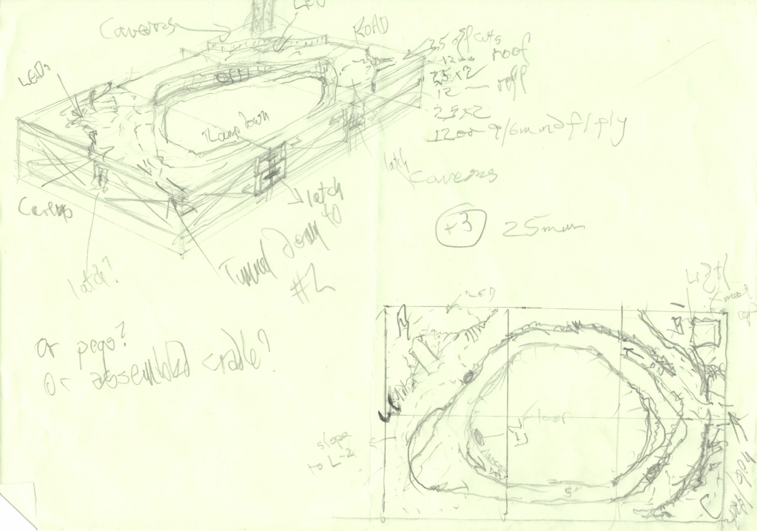
This leads to another design criteria: usability. Reaching across a 6’×4’ table is fine but I didn’t want the depth to make it too awkward: ideally, tunnels and the table centre should be easily accessible by the players. So it looked as if a central, open-cast mine surrounded by tunnelled cliffs would be the most practical and usable design, as well as potentially durable if the right materials were used (we’ll come to that later). Such a design would be flexible as I could even stagger the sides down in plateaus as seen on open-cast mines and perhaps just use one or two layers over a decent base mat if I didn’t want to lug around the whole table.
After several discarded sketches, I came up with the view and plan as shown in figure two. There would be a surface level, plus one or two underground levels. The top layer could have interest in the form of more board built up. If I built them right, I could even build the table layer by layer. I then transferred the plan onto a much bigger scale and mapped out each 2’×2’ square, to give diagram 3 – a large, working plan that I put up on the wall of my work-area.
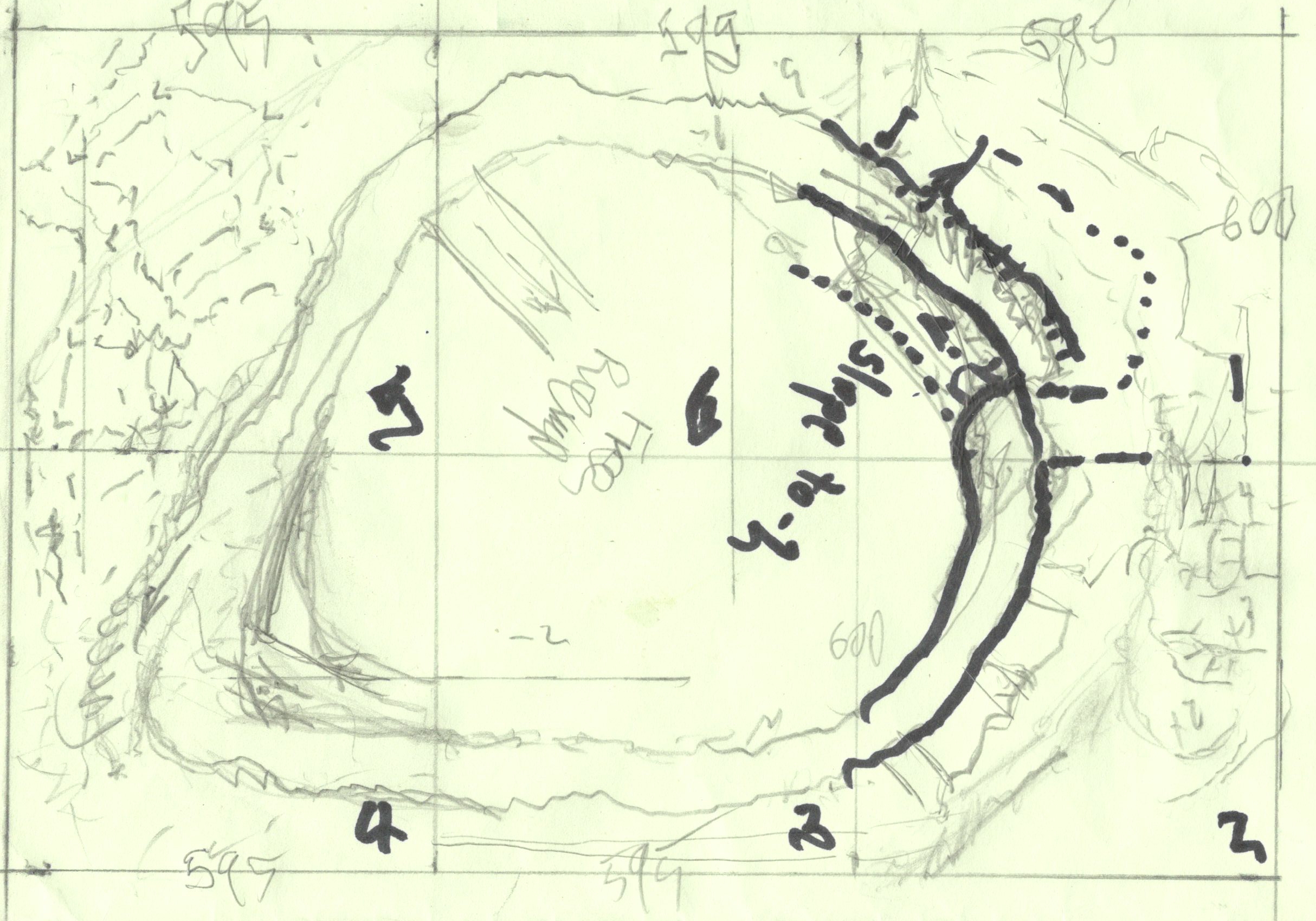
Now, astute observers might notice some measurements on the working plan that don’t quite match the 2’×2’ intention. That’s simply because I did one thing before going ahead with the design, or ordering or cutting: I measured the polyboards. Whilst nominally 600mm across, the polyboards are actually 595mm across by about 2.5m long. Whilst a building site might find this useful, on a wargames table 5mm ends up being rather visible and awkward! A basic truism still stands: measure twice, cut once!
The diagram also shows another useful tip: number each section as you design and work on them as it can get awkward remembering which is which and where they go.
After checking that I had a few supplies (more next time) and tools, I was ready to get underway. The first batch of 6mm mdf for the topmost and the first tunnel layer was to be 10 boards of 595mm×600mm. Having it cut made it a little more expensive, but wanted them cut exactly and neatly as, for a number of reasons, I am not the most accurate with a saw so felt it best to have someone else do the job! These ten boards would give the 8 corner pieces (4×2 layers) plus the two pairs of central pieces – none reached half-way so I could just use each end.
Then the 12mm and 25mm polyboard arrived, already cut in half: at last, I could begin cutting and shaping!
In part 2, I continue with the basic shape, marking out and carving out the boards, plus give some tips as to cheap and usable materials.


2 comments
This was a very intresting and awesome to read! Hopefully there will be more Antares stuff to come.
Comments are closed.